- 您现在的位置:买卖IC网 > Sheet目录312 > AT24C256C-XHL-B (Atmel)IC EEPROM 256KBIT IND 8TSSOP
�� �
�
�5.�
�Memory� Organization�
�Atmel� AT24C256C,� 256K� Serial� EEPROM� :� The� 256K� is� internally� organized� as� 512� pages� of� 64-bytes� each.� Random�
�word� addressing� requires� a� 15-bit� data� word� address.�
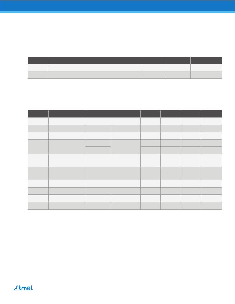
�Table� 5-1.�
�Pin� Capacitance� (1)�
�Applicable� over� recommended� operating� range� from:� T� A� =� 25°C,� f� =� 1.0MHz,� V� CC� =� 1.7V� to� 5.5V.�
�Symbol�
�C� I/O�
�C� IN�
�Note:�
�1.�
�Test� Condition�
�Input/Output� Capacitance� (SDA)�
�Input� Capacitance� (A� 0� ,� A� 1� ,� A� 2� ,� and� SCL)�
�This� parameter� is� characterized� and� is� not� 100%� tested.�
�Max�
�8�
�6�
�Units�
�pF�
�pF�
�Conditions�
�V� I/O� =� 0V�
�V� IN� =� 0V�
�Table� 5-2.�
�DC� Characteristics�
�Applicable� over� recommended� operating� range� from:� T� AI� =� -� 40°C� to� +85°C,� V� CC� =� 1.7V� to� 5.5V� (unless� otherwise� noted)� .�
�Symbol�
�V� CC1�
�I� CC1�
�I� CC2�
�Parameter�
�Supply� Voltage�
�Supply� Current�
�Supply� Current�
�Test� Condition�
�V� CC� =� 5.0V�
�V� CC� =� 5.0V�
�Read� at� 400kHz�
�Write� at� 400kHz�
�Min�
�1.7�
�Typ�
�1.0�
�2.0�
�Max�
�5.5�
�2.0�
�3.0�
�Units�
�V�
�mA�
�mA�
�I� SB1�
�I� LI�
�Standby� Current�
�Input� Leakage�
�Current� V� CC� =� 5.0V�
�V� CC� =� 1.7V�
�V� CC� =� 5.0V�
�V� IN� =� V� CC� or� V� SS�
�V� IN� =� V� CC� or� V� SS�
�0.10�
�1.0�
�6.0�
�3.0�
�?� A�
�?� A�
�?� A�
�I� LO�
�V� IL�
�V� IH�
�Output� Leakage�
�Current� V� CC� =� 5.0V�
�Input� Low� Level� (1)�
�Input� High� Level� (� (1)�
�V� OUT� =� V� CC� or� V� SS�
�-0.6�
�V� CC� x� 0.7�
�0.05�
�3.0�
�V� CC� x� 0.3�
�V� CC� +� 0.5�
�?� A�
�V�
�V�
�V� OL1�
�V� OL2�
�Output� Low� Level�
�Output� Low� Level�
�V� CC� =� 1.7V�
�V� CC� =� 3.0V�
�I� OL� =� 0.15mA�
�I� OL� =� 2.1mA�
�0.2�
�0.4�
�V�
�V�
�Note:�
�1.�
�V� IL� min� and� V� IH� max� are� reference� only� and� are� not� tested.�
�Atmel� AT24C256C� [DATASHEET]�
�8568E–SEEPR–8/2012�
�4�
�发布紧急采购,3分钟左右您将得到回复。
相关PDF资料
AT24C32AY6-10YH-1.8
IC EEPROM 32KBIT 400KHZ 8DFN
AT24C512BY7-YH25-T
IC EEPROM 512KBIT 1MHZ 8SAP
AT24C512W-10SU-1.8
IC EEPROM 512KBIT 400KHZ 8SOIC
AT24C64B-10TU-1.8
IC EEPROM 64KBIT 400KHZ 8TSSOP
AT24C64CY6-YH-T
IC EEPROM 64KBIT 1MHZ 8MLP
AT24C64W-10SI-1.8
IC EEPROM 64KBIT 400KHZ 8SOIC
AT24HC02B-TH-B
IC EEPROM 2KBIT 1MHZ 8TSSOP
AT25040A-10TU-1.8
IC EEPROM 4KBIT 20MHZ 8TSSOP
相关代理商/技术参数
AT24C256C-XHL-T
功能描述:电可擦除可编程只读存储器 256K (32K X 8), 2-WI 1.8V RoHS:否 制造商:Atmel 存储容量:2 Kbit 组织:256 B x 8 数据保留:100 yr 最大时钟频率:1000 KHz 最大工作电流:6 uA 工作电源电压:1.7 V to 5.5 V 最大工作温度:+ 85 C 安装风格:SMD/SMT 封装 / 箱体:SOIC-8
AT24C256C-XPD-T
制造商:Atmel Corporation 功能描述:SERIAL EEPROM, 256K (32K X 8) - Tape and Reel
AT24C256N-10SC
功能描述:IC EEPROM 256KBIT 1MHZ 8SOIC 制造商:microchip technology 系列:- 包装:管件 零件状态:停產 存储器类型:非易失 存储器格式:EEPROM 技术:EEPROM 存储容量:256Kb (32K x 8) 时钟频率:1MHz 写周期时间 - 字,页:10ms 访问时间:550ns 存储器接口:I2C 电压 - 电源:4.5 V ~ 5.5 V 工作温度:0°C ~ 70°C(TA) 安装类型:表面贴装 封装/外壳:8-SOIC(0.154",3.90mm 宽) 供应商器件封装:8-SOIC 基本零件编号:AT24C256 标准包装:100
AT24C256N-10SC-1.8
功能描述:IC EEPROM 256KBIT 400KHZ 8SOIC 制造商:microchip technology 系列:- 包装:管件 零件状态:停產 存储器类型:非易失 存储器格式:EEPROM 技术:EEPROM 存储容量:256Kb (32K x 8) 时钟频率:400kHz 写周期时间 - 字,页:10ms 访问时间:900ns 存储器接口:I2C 电压 - 电源:1.8 V ~ 3.6 V 工作温度:0°C ~ 70°C(TA) 安装类型:表面贴装 封装/外壳:8-SOIC(0.154",3.90mm 宽) 供应商器件封装:8-SOIC 基本零件编号:AT24C256 标准包装:100
AT24C256N-10SC-2.7
功能描述:IC EEPROM 256KBIT 1MHZ 8SOIC RoHS:否 类别:集成电路 (IC) >> 存储器 系列:- 标准包装:32 系列:- 格式 - 存储器:闪存 存储器类型:FLASH 存储容量:1M (128K x 8) 速度:120ns 接口:并联 电源电压:2.7 V ~ 3.6 V 工作温度:0°C ~ 70°C 封装/外壳:32-LCC(J 形引线) 供应商设备封装:32-PLCC 包装:管件 其它名称:AT49BV00112JC
AT24C256N-10SI
功能描述:IC EEPROM 256KBIT 1MHZ 8SOIC RoHS:否 类别:集成电路 (IC) >> 存储器 系列:- 标准包装:32 系列:- 格式 - 存储器:闪存 存储器类型:FLASH 存储容量:1M (128K x 8) 速度:120ns 接口:并联 电源电压:2.7 V ~ 3.6 V 工作温度:0°C ~ 70°C 封装/外壳:32-LCC(J 形引线) 供应商设备封装:32-PLCC 包装:管件 其它名称:AT49BV00112JC
AT24C256N-10SI-1.8
功能描述:IC EEPROM 256KBIT 400KHZ 8SOIC RoHS:否 类别:集成电路 (IC) >> 存储器 系列:- 标准包装:32 系列:- 格式 - 存储器:闪存 存储器类型:FLASH 存储容量:1M (128K x 8) 速度:120ns 接口:并联 电源电压:2.7 V ~ 3.6 V 工作温度:0°C ~ 70°C 封装/外壳:32-LCC(J 形引线) 供应商设备封装:32-PLCC 包装:管件 其它名称:AT49BV00112JC
AT24C256N-10SI-2.7
功能描述:IC EEPROM 256KBIT 1MHZ 8SOIC RoHS:否 类别:集成电路 (IC) >> 存储器 系列:- 标准包装:32 系列:- 格式 - 存储器:闪存 存储器类型:FLASH 存储容量:1M (128K x 8) 速度:120ns 接口:并联 电源电压:2.7 V ~ 3.6 V 工作温度:0°C ~ 70°C 封装/外壳:32-LCC(J 形引线) 供应商设备封装:32-PLCC 包装:管件 其它名称:AT49BV00112JC